Sophos XGS HA (Active / Passive) - ArubaOS-CX OSPF Routing - ACL
Hello there,
Today, I want to take a look at how to set up a Sophos HA Cluster connected to a layer 3 core switching. We will leave the local routing to the Aruba Switches and just handle the internet traffic on the Sophos Firewalls.
I have a similar post, but that just touched on the configuration of OSPF between a single Sophos XG and Aruba Switch. In that post, I also show how to set up authentication between the OSPF partners and the CLI-based configuration of the Sophos XG. If that's something that interests you, check it out.
I struggled with this at first. I just couldn't wrap my head around this. Since we have a passive firewall that will take over the same IP addresses as the primary system in case of a failure, I won't be able to use different IP addresses on the uplink ports on the core switches. I also can't use the same IP on different ports on the Aruba switches.
It took longer than it should have, but I think I figured it out.
Here is the topology.
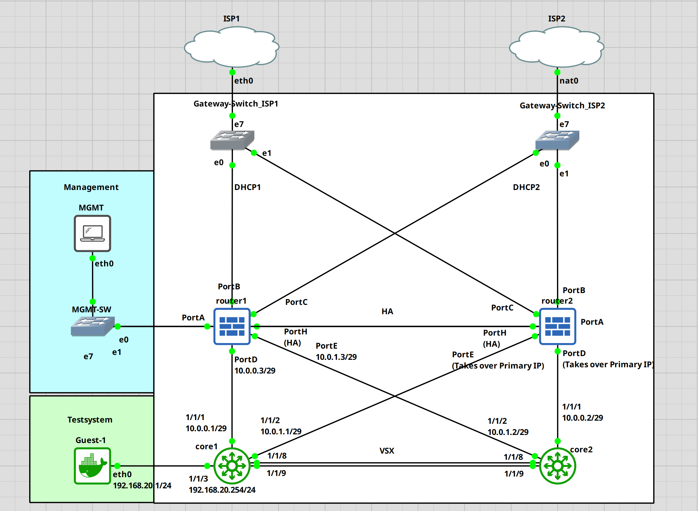
For this guide, I am assuming that the Sophos cluster is already up and running. I have a guide on this if you want to check that out first. Keep in mind that I am no expert in this, these are just my findings through trial and error. I am certain that there is a more optimal way to do this.
I will start with the core switches. We need to set up VSX and a few other things first before configuring OSPF.
Core1 configuration
First, let's set the hostname. I will name the switches core1 and core2.
switch# confswitch(config)# hostname core1core1(config)#
VSX
Next, we will configure the VLAN, interfaces for VSX and VSX itself. I have a separate guide on this with a little bit more detail.
# Creating a vrf to keep the keepalive traffic separated core1(config)# vrf KEEPALIVEcore1(config-vrf)# exit # Create a vlan, attach it to the newly created vrf and assign a IP address core1(config)# vlan 255core1(config-vlan-255)# exit core1(config)# interface vlan 255core1(config-if-vlan)# vrf attach KEEPALIVEcore1(config-if-vlan)# ip address 192.168.255.1/30core1(config-if-vlan)# exit # Setup a LAG for the VSX ISL core1(config)# interface lag 255core1(config-lag-if)# no shutdowncore1(config-lag-if)# no routingcore1(config-lag-if)# vlan trunk native 1core1(config-lag-if)# lacp mode activecore1(config-lag-if)# exit core1(config)# interface 1/1/8-1/1/9core1(config-if-<1/1/8-1/1/9>)# no shutdowncore1(config-if-<1/1/8-1/1/9>)# lag 255core1(config-if-<1/1/8-1/1/9>)# exit # Configure VSX core1(config)# vsxcore1(config-vsx)# inter-switch-link lag 255core1(config-vsx)# keepalive peer 192.168.255.2 source 192.168.255.1 vrf KEEPALIVEcore1(config-vsx)# system-mac e0:00:00:00:00:01core1(config-vsx)# role primarycore1(config-vsx)# vsx-sync vsx-global ospf mclag-interfaces static-routescore1(config-vsx)# exit
Interface
Now, we will set up interfaces 1/1/1 and 1/1/2 for the uplink to the Sophos XGS and the loopback interface for OSPF. Take note of the /29 network. This will allow the switches to establish a connection with the passive device in case of a failure.
core1(config)# interface 1/1/1core1(config-if)# no shutdowncore1(config-if)# ip address 10.0.0.1/29core1(config-if)# exit core1(config)# interface 1/1/2core1(config-if)# no shutdowncore1(config-if)# ip address 10.0.1.1/29core1(config-if)# exit core1(config)# interface loopback 0core1(config-loopback-if)# ip add 10.255.255.1/32core1(config-loopback-if)# exitcore1(config)#
OSPF
Setting up OSPF. I will set up the bare minimum to get it running.
core1(config)# router ospf 1core1(config-ospf-1)# area 0.0.0.0core1(config-ospf-1)# passive-interface defaultcore1(config-ospf-1)# exit core1(config)# interface loopback 0core1(config-loopback-if)# ip ospf 1 area 0core1(config-loopback-if)# exit core1(config)# interface 1/1/1-1/1/2core1(config-if-<1/1/1-1/1/2>)# ip ospf 1 area 0core1(config-if-<1/1/1-1/1/2>)# no ip ospf passivecore1(config-if-<1/1/1-1/1/2>)# exit
Transit VLAN
Let's set up a transit VLAN for the OSPF traffic between the VSX switches.
# Creating the transit VLAN core1(config)# vlan 254core1(config-vlan-254)# interface vlan 254core1(config-if-vlan)# ip add 192.168.254.1/30core1(config-if-vlan)# ip ospf 1 area 0core1(config-if-vlan)# no ip ospf passivecore1(config-if-vlan)# ip ospf cost 50core1(config-if-vlan)# ip ospf network point-to-point
This is it for the first switch. At the bottom of this post, I will add the whole running-configuration.
Let's do the same for core2
Core2 configuration
Again. Setting the hostname.
switch# confarubaos-cx(config)# hostname core2core2(config)#
VSX
Setting up VSX. We just need to change the IP addresses and the VSX role. The rest is the same.
core2(config)# vrf KEEPALIVEcore2(config-vrf)# exit core2(config)# vlan 255core2(config-vlan-255)# exit core2(config)# interface vlan 255core2(config-if-vlan)# vrf attach KEEPALIVEcore2(config-if-vlan)# ip address 192.168.255.2/30core2(config-if-vlan)# exit core2(config)# interface lag 255core2(config-lag-if)# no shutdowncore2(config-lag-if)# no routingcore2(config-lag-if)# vlan trunk native 1core2(config-lag-if)# lacp mode activecore2(config-lag-if)# exit core2(config)# interface 1/1/8-1/1/9core2(config-if-<1/1/8-1/1/9>)# no shutdowncore2(config-if-<1/1/8-1/1/9>)# lag 255core2(config-if-<1/1/8-1/1/9>)# exit core2(config)# vsxcore2(config-vsx)# inter-switch-link lag 255core2(config-vsx)# keepalive peer 192.168.255.1 source 192.168.255.2 vrf KEEPALIVEcore2(config-vsx)# system-mac e0:00:00:00:00:01core2(config-vsx)# role secondarycore2(config-vsx)# exit
Interfaces
Again. Making sure that we use a /29 network for the uplink interfaces.
core2(config)# interface 1/1/1core2(config-if)# no shutdowncore2(config-if)# ip address 10.0.0.2/29core2(config-if)# exit core2(config)# interface 1/1/2core2(config-if)# no shutdowncore2(config-if)# ip address 10.0.1.2/29core2(config-if)# exit core2(config)# interface loopback 0core2(config-loopback-if)# ip add 10.255.255.2/32core2(config-loopback-if)# exitcore2(config)#
OSPF
core2(config)# router ospf 1core2(config-ospf-1)# area 0.0.0.0core2(config-ospf-1)# passive-interface defaultcore2(config-ospf-1)# exit core2(config)# interface loopback 0core2(config-loopback-if)# ip ospf 1 area 0core2(config-loopback-if)# exit core2(config)# interface 1/1/1-1/1/2core2(config-if-<1/1/1-1/1/2>)# ip ospf 1 area 0core2(config-if-<1/1/1-1/1/2>)# no ip ospf passivecore2(config-if-<1/1/1-1/1/2>)# exit
Transit VLAN
core2(config)# vlan 254core2(config-vlan-254)# interface vlan 254core2(config-if-vlan)# ip add 192.168.254.2/30core2(config-if-vlan)# ip ospf 1 area 0core2(config-if-vlan)# no ip ospf passivecore2(config-if-vlan)# ip ospf cost 50core2(config-if-vlan)# ip ospf network point-to-point
At this point, our VSX cluster should work. We can check this with the "show vsx status" command.
core1(config)# show vsx statusVSX Operational State --------------------- ISL channel : In-Sync ISL mgmt channel : operational Config Sync Status : In-Sync NAE : peer_reachable HTTPS Server : peer_reachable Attribute Local Peer ------------ -------- -------- ISL link lag255 lag255 ISL version 2 2 System MAC e0:00:00:00:00:01 e0:00:00:00:00:01 Platform X86-64 X86-64 Software Version Virtual.10.11.0001 Virtual.10.11.0001 Device Role primary secondary
Everything is reachable and in sync. Looks fine.
The switches are done. Let's set up the Sophos XGS. Like I said before, I assume that the HA and basic configuration are done.
Sophos XGS Configuration (Network, OSPF)
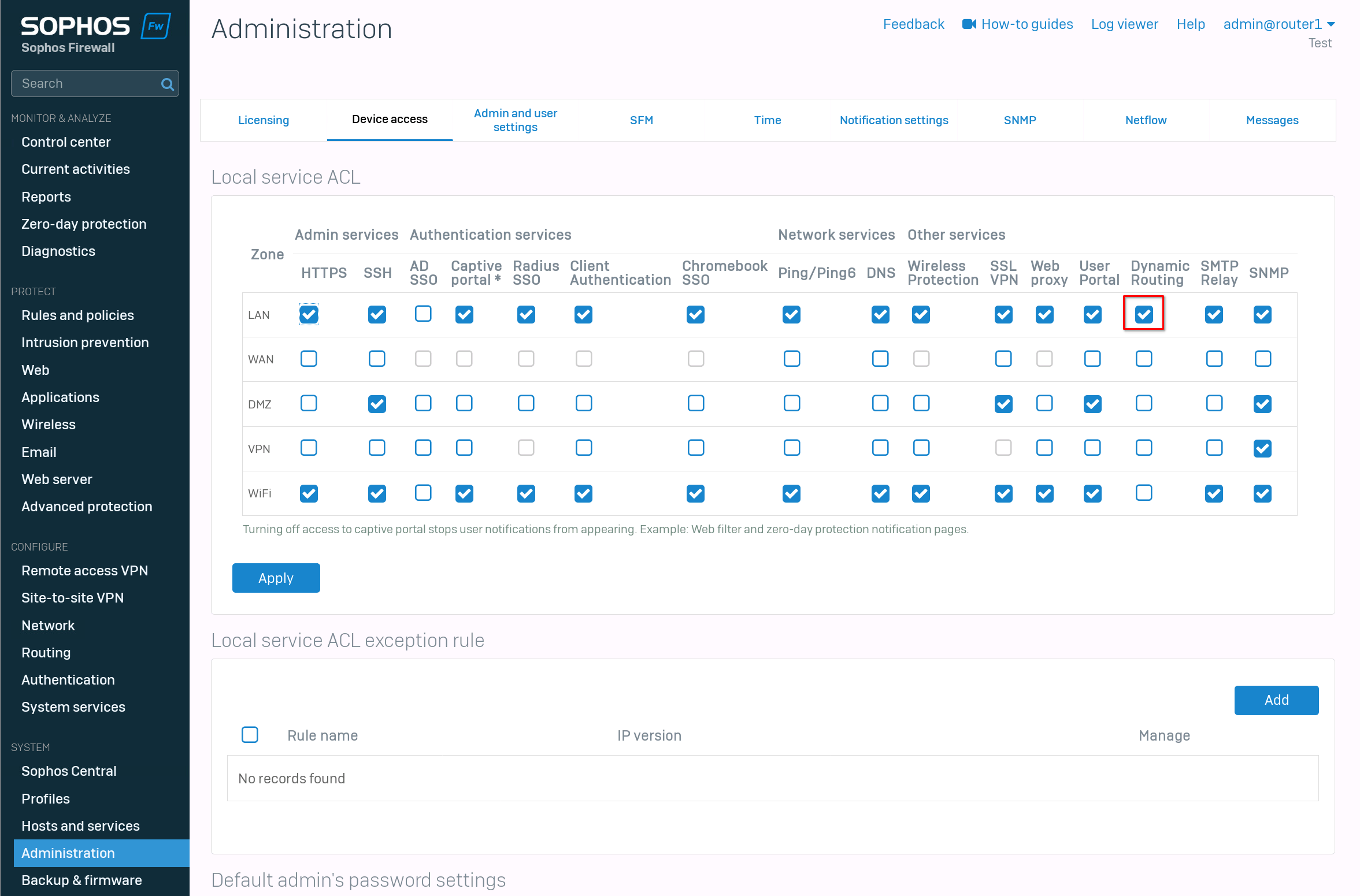
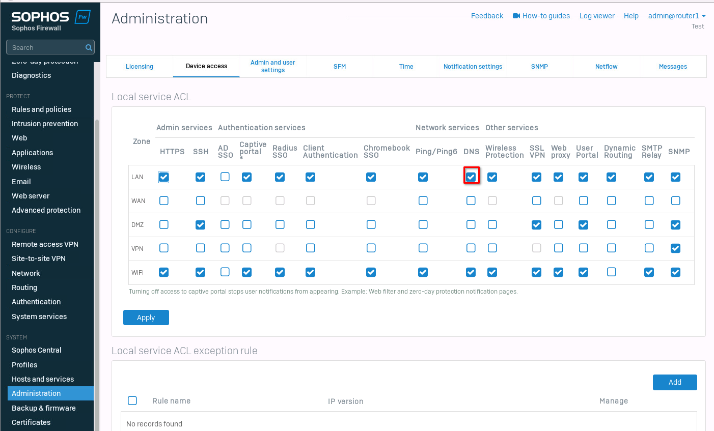
First, we need to enable "dynamic routing" on the "LAN" zone. For this, navigate to "Administration" -> "Device access" and enable dynamic routing.
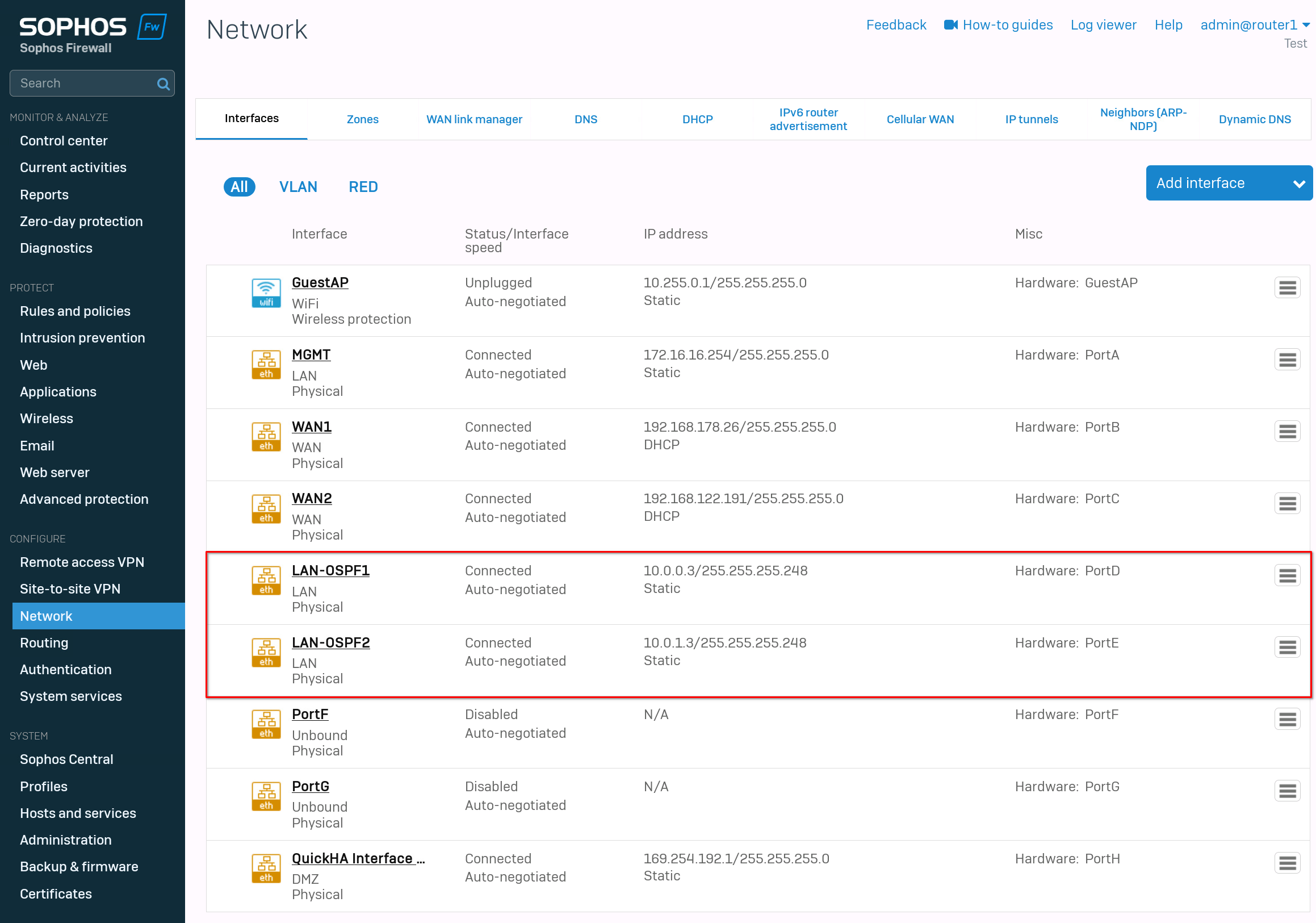
After that, we can configure the interfaces. Go to "network" -> "interfaces". If you follow this guide exactly, then set PortD to "10.0.0.3/29" and PortE to "10.0.1.3/29". The rest of the interfaces are up to you. I used PortA as a management port and PortB, PortC for the wan network.
The last port, PortH is my heartbeat for the HA cluster.
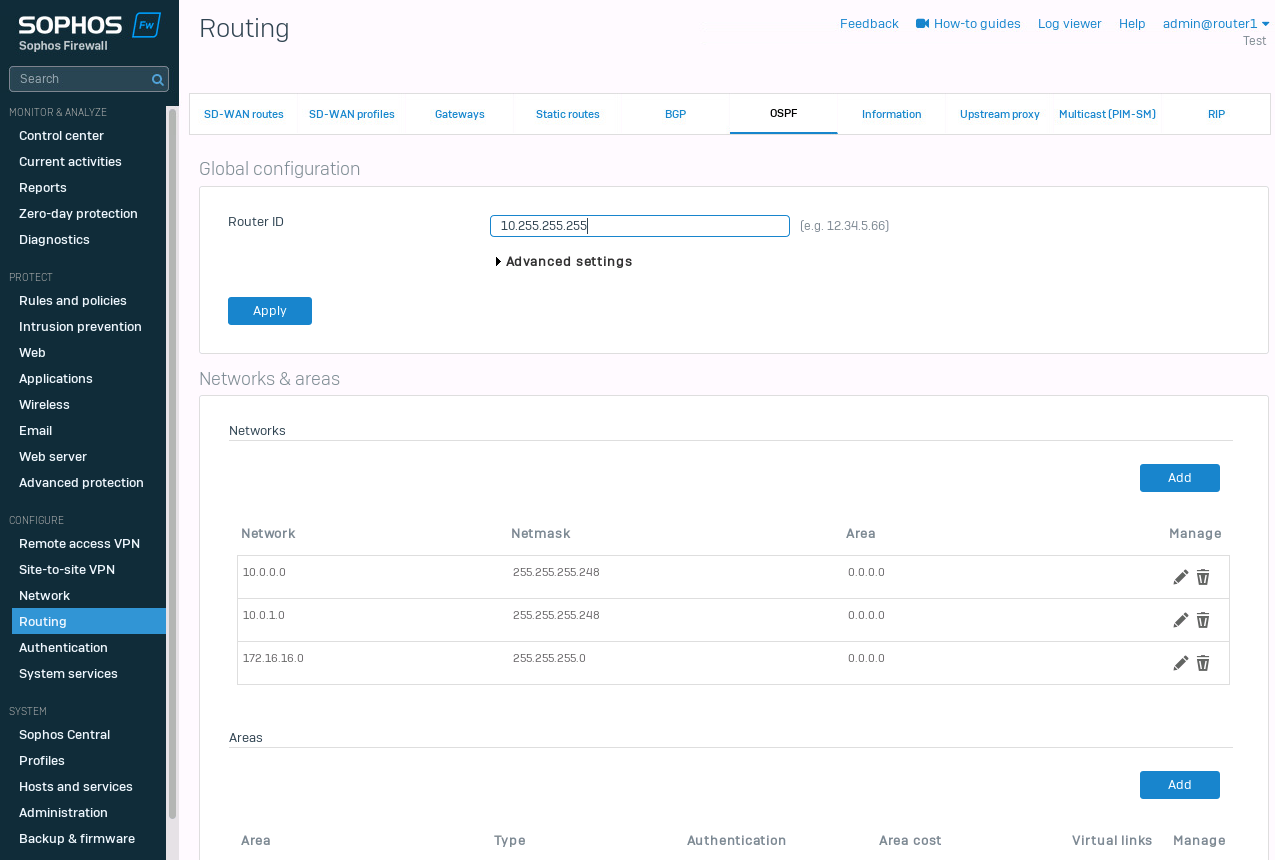
The last step is the OSPF configuration. Navigate to "Routing" -> "OSPF". Set the Router-ID. I choose "10.255.255.255". Within the "Advanced settings" we have the "Default information originate". I set this to "Always". This should propagate the default route to the switches.
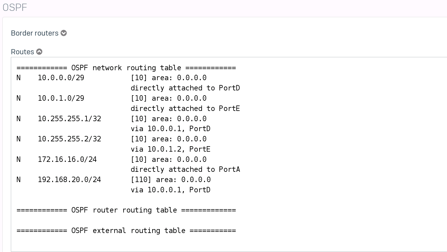
For the "Networks & areas", I set the 3 networks I have currently configured. 10.0.0.0/29, 10.0.1.0/29 and 172.16.16.0/24.
That's it. At this point, we should see the new routes on our core switches and the Sophos Firewall.
Verifying the routes
Let's check the Sophos XGS first. Navigate to "Routing" -> "Information" and select "Routes" under OSPF.
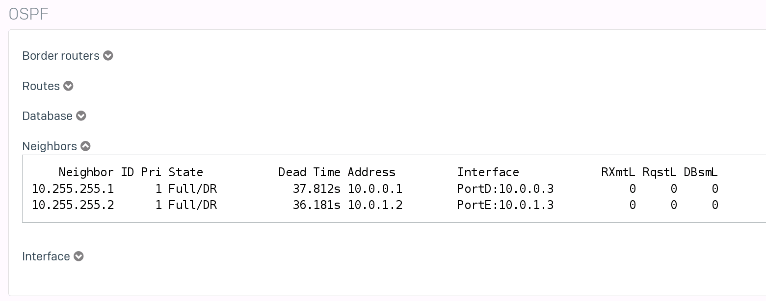
While we are at it. Let's also take a look at the OSPF neighbors.
Next, we will check the switches.
core1(config)# show ip route Displaying ipv4 routes selected for forwarding Origin Codes: C - connected, S - static, L - local R - RIP, B - BGP, O - OSPF Type Codes: E - External BGP, I - Internal BGP, V - VPN, EV - EVPN IA - OSPF internal area, E1 - OSPF external type 1 E2 - OSPF external type 2 VRF: default Prefix Nexthop Interface VRF(egress) Origin/ Distance/ Age Type Metric -------------------------------------------------------------------------------------------------------- 0.0.0.0/0 10.0.0.3 1/1/1 - O/E2 [110/1] 00h:01m:07s 10.0.0.0/29 - 1/1/1 - C [0/0] - 10.0.0.1/32 - 1/1/1 - L [0/0] - 10.0.1.0/29 - 1/1/2 - C [0/0] - 10.0.1.1/32 - 1/1/2 - L [0/0] - 10.255.255.1/32 - loopback0 - L [0/0] - 10.255.255.2/32 10.0.0.3 1/1/1 - O [110/110] 00h:20m:04s 172.16.16.0/24 10.0.0.3 1/1/1 - O [110/110] 00h:20m:00s Total Route Count : 8 core1(config)# show ip ospf routeCodes: i - Intra-area route, I - Inter-area route E1 - External type-1, E2 - External type-2 OSPF Process ID 1 VRF default, Routing Table --------------------------------------------- Total Number of Routes : 5 0.0.0.0/0 (E2) via 10.0.0.3 interface 1/1/1, cost 1 distance 11010.0.0.0/29 (i) area: 0.0.0.0 directly attached to interface 1/1/1, cost 100 distance 110 10.0.1.0/29 (i) area: 0.0.0.0 directly attached to interface 1/1/2, cost 100 distance 110 10.255.255.2/32 (i) area: 0.0.0.0 via 10.0.0.3 interface 1/1/1, cost 110 distance 110 172.16.16.0/24 (i) area: 0.0.0.0 via 10.0.0.3 interface 1/1/1, cost 110 distance 110
And on the Core2 switch.
core2(config)# show ip route Displaying ipv4 routes selected for forwarding Origin Codes: C - connected, S - static, L - local R - RIP, B - BGP, O - OSPF Type Codes: E - External BGP, I - Internal BGP, V - VPN, EV - EVPN IA - OSPF internal area, E1 - OSPF external type 1 E2 - OSPF external type 2 VRF: default Prefix Nexthop Interface VRF(egress) Origin/ Distance/ Age Type Metric -------------------------------------------------------------------------------------------------------- 0.0.0.0/0 10.0.1.3 1/1/2 - O/E2 [110/1] 00h:02m:16s 10.0.0.0/29 - 1/1/1 - C [0/0] - 10.0.0.2/32 - 1/1/1 - L [0/0] - 10.0.1.0/29 - 1/1/2 - C [0/0] - 10.0.1.2/32 - 1/1/2 - L [0/0] - 10.255.255.1/32 10.0.1.3 1/1/2 - O [110/110] 00h:21m:10s 10.255.255.2/32 - loopback0 - L [0/0] - 172.16.16.0/24 10.0.1.3 1/1/2 - O [110/110] 00h:21m:10s Total Route Count : 8
Testing Failover
Let's see what happens, when the primary firewall disappears. I will just shut it off. To test the behavior, I will send a (almost) continuous ping to "1.1.1.1" from one of the cores. We will also check the routes afterward.
core2(config)# ping 1.1.1.1 repetitions 1000... ... 108 bytes from 1.1.1.1: icmp_seq=9 ttl=51 time=27.1 ms 108 bytes from 1.1.1.1: icmp_seq=10 ttl=51 time=23.3 ms 108 bytes from 1.1.1.1: icmp_seq=11 ttl=51 time=27.0 ms 108 bytes from 1.1.1.1: icmp_seq=12 ttl=51 time=24.2 ms ping4: sendmsg: Network is unreachable ping4: sendmsg: Network is unreachable ping4: sendmsg: Network is unreachable From 10.0.0.3 icmp_seq=47 Destination Net Unreachable From 10.0.0.3 icmp_seq=48 Destination Net Unreachable From 10.0.0.3 icmp_seq=49 Destination Net Unreachable 108 bytes from 1.1.1.1: icmp_seq=50 ttl=52 time=27.6 ms 108 bytes from 1.1.1.1: icmp_seq=51 ttl=52 time=26.2 ms 108 bytes from 1.1.1.1: icmp_seq=52 ttl=52 time=25.4 ms
The switchover took around 10-20sec, and we lost around 40 pings.
And here are the new routes on the core2.
core2(config)# show ip route Displaying ipv4 routes selected for forwarding Origin Codes: C - connected, S - static, L - local R - RIP, B - BGP, O - OSPF Type Codes: E - External BGP, I - Internal BGP, V - VPN, EV - EVPN IA - OSPF internal area, E1 - OSPF external type 1 E2 - OSPF external type 2 VRF: default Prefix Nexthop Interface VRF(egress) Origin/ Distance/ Age Type Metric -------------------------------------------------------------------------------------------------------- 0.0.0.0/0 10.0.0.3 1/1/1 - O/E2 [110/1] 00h:00m:46s 10.0.0.0/29 - 1/1/1 - C [0/0] - 10.0.0.2/32 - 1/1/1 - L [0/0] - 10.0.1.0/29 - 1/1/2 - C [0/0] - 10.0.1.2/32 - 1/1/2 - L [0/0] - 10.255.255.1/32 10.0.0.3 1/1/1 - O [110/110] 00h:00m:46s 10.255.255.2/32 - loopback0 - L [0/0] - 172.16.16.0/24 10.0.0.3 1/1/1 - O [110/110] 00h:00m:46s
We can see that the IP for the "nexthop" changed.
I tried to lower the switchover time. I would like to test BFD, but as far as I am aware, Sophos does not support it.
Trying to adjust the dead-interval and hello-interval didn't really change anything.
So unfortunately, this whole process does not allow a smooth failover, even when manually switching to the passive device.
Firewall Rules
While we are at it, why not take a look at how to correctly set firewall rules. To test the rules, we will set up a test network on one of the core switches.
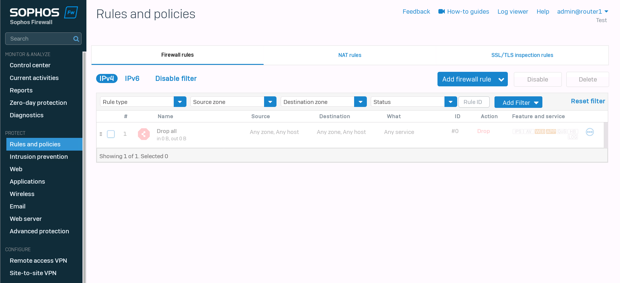
I removed every firewall rule on the Sophos Firewalls, so we can start with a clean slate.
Test network configuration
We will create a test network and distribute it with OSPF on core1 first.
core1(config)# interface 1/1/3core1(config-if)# no shutdowncore1(config-if)# ip address 192.168.20.254/24core1(config-if)# ip ospf 1 area 0core1(config-if)# no ip ospf passive
Testing ping
I gave the client the IP address 192.168.20.2/24. First, we should check if we can reach our default gateway.
fedora-kde :: ~ » ifconfig eth0 192.168.20.2/24fedora-kde :: ~ » ping 192.168.20.254PING 192.168.20.254 (192.168.20.254) 56(84) bytes of data. 64 bytes from 192.168.20.254: icmp_seq=1 ttl=64 time=2.01 ms 64 bytes from 192.168.20.254: icmp_seq=2 ttl=64 time=1.83 ms 64 bytes from 192.168.20.254: icmp_seq=3 ttl=64 time=1.70 ms
Creating default route
Great. Next, we should set the default route.
fedora-kde :: ~ » ip route add default via 192.168.20.254fedora-kde :: ~ » routeKernel IP routing table Destination Gateway Genmask Flags Metric Ref Use Iface default 192.168.20.254 0.0.0.0 UG 0 0 0 eth0 192.168.20.0 * 255.255.255.0 U 0 0 0 eth0
Second test ping
Let's ping the Sophos Firewall.
fedora-kde :: ~ » ping 10.0.0.3 -c3PING 10.0.0.3 (10.0.0.3) 56(84) bytes of data. 64 bytes from 10.0.0.3: icmp_seq=1 ttl=63 time=2.29 ms 64 bytes from 10.0.0.3: icmp_seq=2 ttl=63 time=1.83 ms 64 bytes from 10.0.0.3: icmp_seq=3 ttl=63 time=2.27 ms --- 10.0.0.3 ping statistics --- 3 packets transmitted, 3 received, 0% packet loss, time 2003ms rtt min/avg/max/mdev = 1.835/2.132/2.290/0.210 ms fedora-kde :: ~ » ping 10.0.1.3 -c3PING 10.0.1.3 (10.0.1.3) 56(84) bytes of data. From 192.168.20.254 icmp_seq=1 Destination Host Unreachable From 192.168.20.254 icmp_seq=2 Destination Host Unreachable From 192.168.20.254 icmp_seq=3 Destination Host Unreachable --- 10.0.1.3 ping statistics --- 3 packets transmitted, 0 received, +3 errors, 100% packet loss, time 2024ms pipe 3
The ping to the second IP failed. This is most likely caused by the simulation in GNS3. Since the Aruba switches have no way of verifying if a physical link is active or not. Disabling the interface 1/1/2 on the first and 1/1/1 on the second switch respectively corrects the routes and traffic flow.
core1(config)# interface 1/1/2core1(config-if)# shutdowncore1(config-if)# show ip routeDisplaying ipv4 routes selected for forwarding Origin Codes: C - connected, S - static, L - local R - RIP, B - BGP, O - OSPF Type Codes: E - External BGP, I - Internal BGP, V - VPN, EV - EVPN IA - OSPF internal area, E1 - OSPF external type 1 E2 - OSPF external type 2 VRF: default Prefix Nexthop Interface VRF(egress) Origin/ Distance/ Age Type Metric -------------------------------------------------------------------------------------------------------- 0.0.0.0/0 10.0.0.3 1/1/1 - O/E2 [110/1] 01h:10m:24s 10.0.0.0/29 - 1/1/1 - C [0/0] - 10.0.0.1/32 - 1/1/1 - L [0/0] - 10.0.1.0/29 10.0.0.3 1/1/1 - O [110/110] 00h:00m:41s 10.255.255.1/32 - loopback0 - L [0/0] - 10.255.255.2/32 192.168.254.2 vlan254 - O [110/50] 00h:46m:15s 172.16.16.0/24 10.0.0.3 1/1/1 - O [110/110] 01h:10m:24s 192.168.20.0/24 - 1/1/3 - C [0/0] - 192.168.20.254/32 - 1/1/3 - L [0/0] - 192.168.254.0/30 - vlan254 - C [0/0] - 192.168.254.1/32 - vlan254 - L [0/0] - Total Route Count : 11
Testing the ping again.
fedora-kde :: ~ » ping 10.0.1.3 -c3PING 10.0.1.3 (10.0.1.3) 56(84) bytes of data. 64 bytes from 10.0.1.3: icmp_seq=1 ttl=63 time=2.13 ms 64 bytes from 10.0.1.3: icmp_seq=2 ttl=63 time=1.19 ms 64 bytes from 10.0.1.3: icmp_seq=3 ttl=63 time=1.45 ms --- 10.0.1.3 ping statistics --- 3 packets transmitted, 3 received, 0% packet loss, time 2001ms rtt min/avg/max/mdev = 1.199/1.594/2.132/0.395 ms
Testing ping to WAN
Great. Now let's ping 1.1.1.1
fedora-kde :: ~ » ping 1.1.1.1 -c2PING 1.1.1.1 (1.1.1.1) 56(84) bytes of data. --- 1.1.1.1 ping statistics --- 2 packets transmitted, 0 received, 100% packet loss, time 1009ms
As expected, it does not work. Let's create a firewall rule.
Creating the first Rule
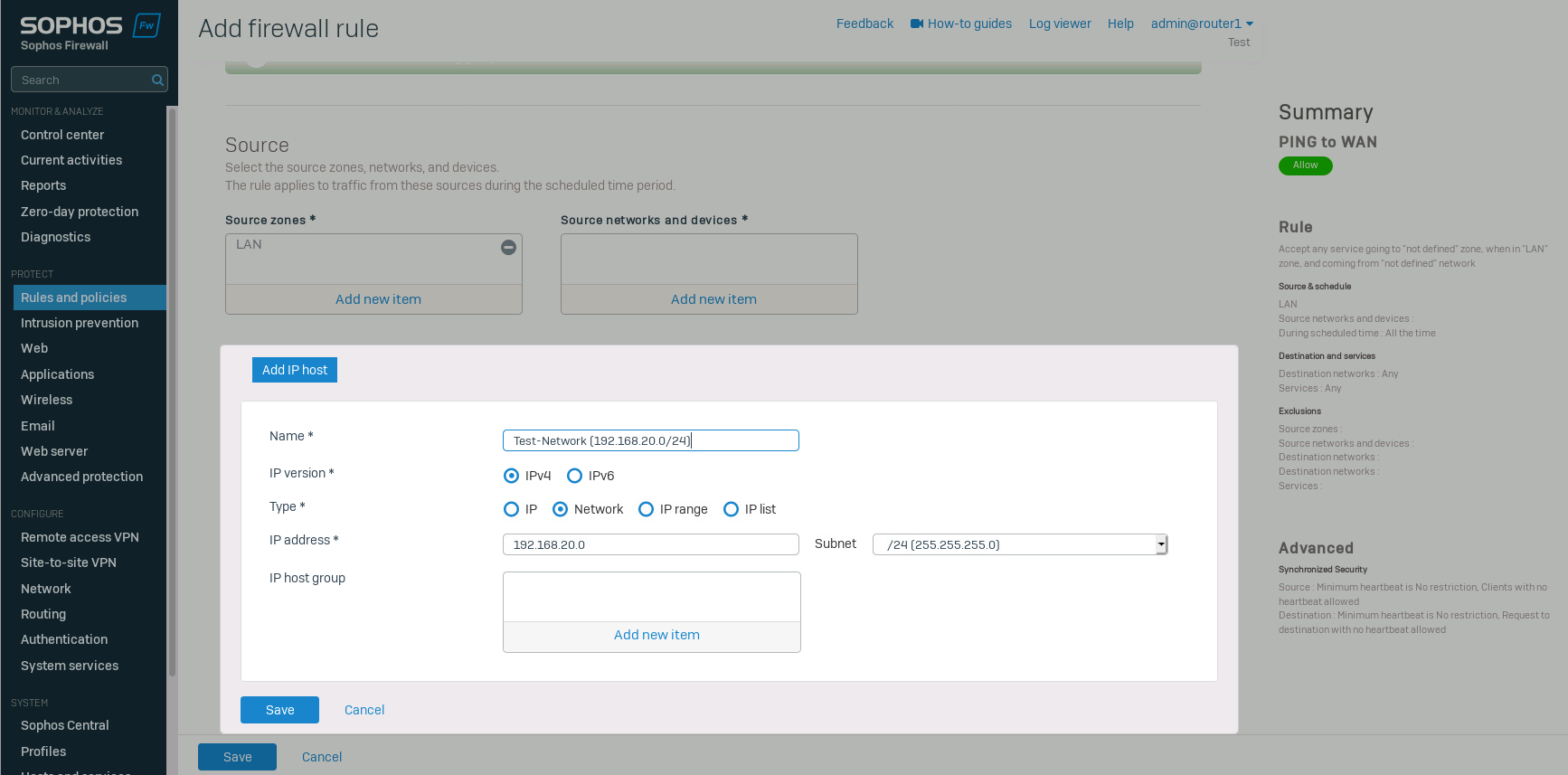
Navigate to "Rules and policies" and click on "Add firewall rule" -> "New firewall rule". Select the source zone and add a new network in "source networks and devices".
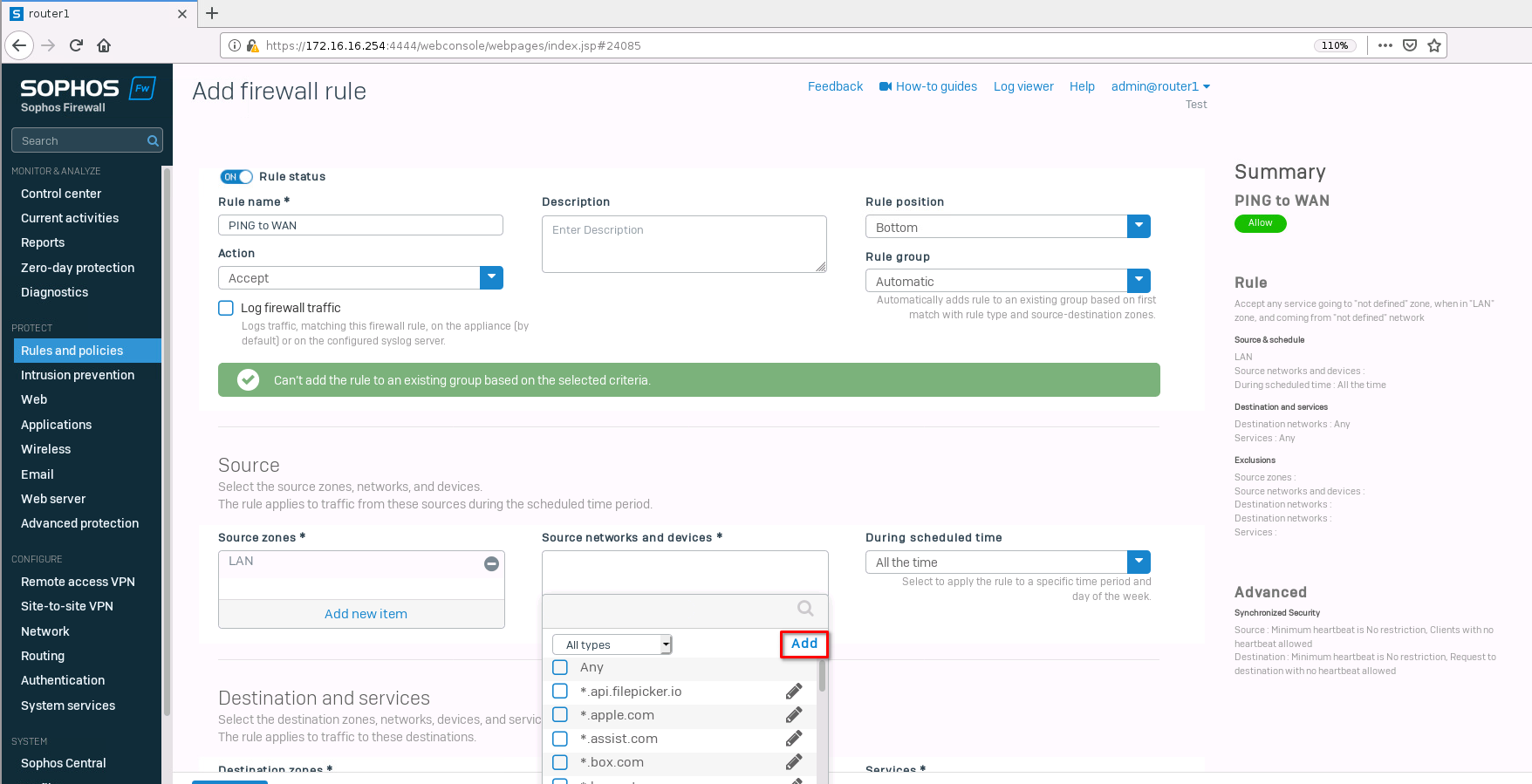
Type in the test network we created earlier and save it.
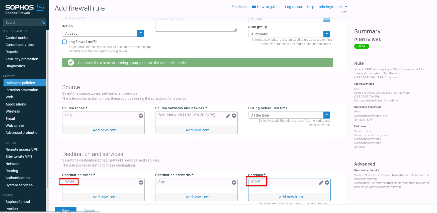
Select "WAN" for the "destination zone" and "ICMP" for the "Services". Save the new rule.
Now we can test the ping again.
fedora-kde :: ~ » ping 1.1.1.1 -c2PING 1.1.1.1 (1.1.1.1) 56(84) bytes of data. 64 bytes from 1.1.1.1: icmp_seq=1 ttl=50 time=36.4 ms 64 bytes from 1.1.1.1: icmp_seq=2 ttl=50 time=23.3 ms --- 1.1.1.1 ping statistics --- 2 packets transmitted, 2 received, 0% packet loss, time 1001ms rtt min/avg/max/mdev = 23.314/29.861/36.409/6.549 ms
Let's create one more rule for web browsing. It's the same rule for the most part. Just add HTTP and HTTPs to the Services and make sure that DNS is allowed for the WAN zone (this is the default behavior). If you want to use an external DNS server, you need to add DNS to the firewall rule.
I go into a bit more detail on how to set up the firewall rules in this post.
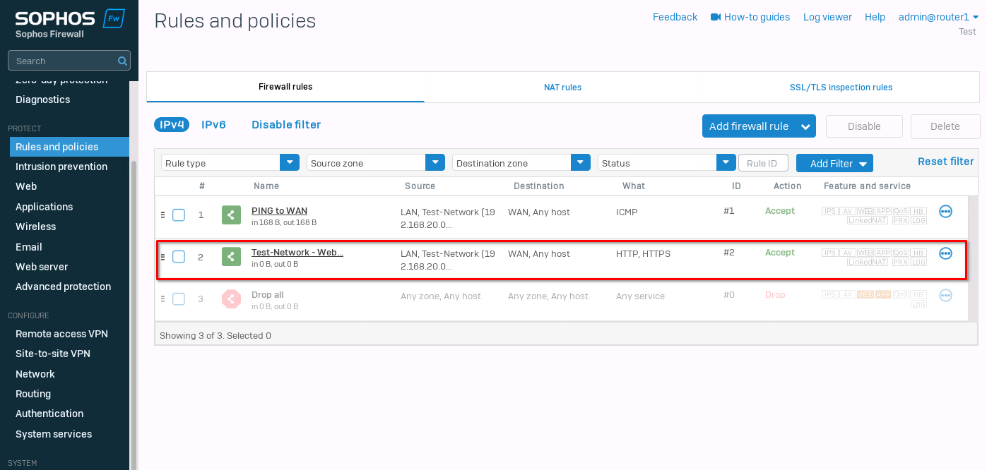
That's it. Now web browsing should also work. Make sure that the DNS settings on your client are correct.
ArubaOS-CX ACL configuration
The last thing I want to test is ACL to control traffic on the core switches. For this, I created another network on the core2 switch.
core2(config)# interface 1/1/3core2(config-if)# no shutdowncore2(config-if)# ip address 192.168.30.254/24core2(config-if)# ip ospf 1 area 0core2(config-if)# no ip ospf passive
The first client has the IP address 192.168.20.2/24, and the second one 192.168.30.2/24. Let's test the reachability between the clients.
client1 :: ~ » ping 192.168.30.2 -c2PING 192.168.30.2 (192.168.30.2) 56(84) bytes of data. 64 bytes from 192.168.30.2: icmp_seq=1 ttl=62 time=3.66 ms 64 bytes from 192.168.30.2: icmp_seq=2 ttl=62 time=4.29 ms --- 192.168.30.2 ping statistics --- 2 packets transmitted, 2 received, 0% packet loss, time 1001ms rtt min/avg/max/mdev = 3.662/3.977/4.293/0.321 ms
It should also work in the other direction, but let's verify.
client2 :: ~ » ping 192.168.20.2 -c2PING 192.168.20.2 (192.168.20.2) 56(84) bytes of data. 64 bytes from 192.168.20.2: icmp_seq=1 ttl=62 time=3.71 ms 64 bytes from 192.168.20.2: icmp_seq=2 ttl=62 time=4.59 ms --- 192.168.20.2 ping statistics --- 2 packets transmitted, 2 received, 0% packet loss, time 1001ms rtt min/avg/max/mdev = 3.719/4.155/4.592/0.441 ms
Alright. Next, we want to create an ACL to control the traffic. I don't want the two networks to be able to communicate with each other but still allow traffic to different networks.
core1(config)# access-list ip FILTER_TEST_NETWORK_Acore1(config-acl-ip)# deny any 192.168.30.0/24 192.168.20.0/24core1(config-acl-ip)# deny any 192.168.20.0/24 192.168.30.0/24core1(config-acl-ip)# permit any any any# This syncs the ACL to the secondary switch core1(config-acl-ip)# vsx-sync
Next, we need to apply the settings to an interface, in our case the interface with the test network.
core1(config)# interface 1/1/3core1(config-if)# apply access-list ip FILTER_TEST_NETWORK_A in
It should be enough to set this on either switch, but I will apply it to both to be consistent.
core2(config)# interface 1/1/3core2(config-if)# apply access-list ip FILTER_TEST_NETWORK_A in
Testing connectivity again.
client2 :: ~ » ping 192.168.20.2 -c2PING 192.168.20.2 (192.168.20.2) 56(84) bytes of data. --- 192.168.20.2 ping statistics --- 2 packets transmitted, 0 received, 100% packet loss, time 1020ms client2 :: ~ » ping 1.1.1.1 -c2PING 1.1.1.1 (1.1.1.1) 56(84) bytes of data. 64 bytes from 1.1.1.1: icmp_seq=1 ttl=51 time=25.1 ms 64 bytes from 1.1.1.1: icmp_seq=2 ttl=51 time=30.6 ms --- 1.1.1.1 ping statistics --- 2 packets transmitted, 2 received, 0% packet loss, time 1001ms rtt min/avg/max/mdev = 25.161/27.901/30.642/2.745 ms
We cannot reach the other test network, but internet traffic still works. Great.
If we want to deny HTTPs (443/TCP) on the switch level, we can add it to the ACL.
core1(config)# access-list ip FILTER_TEST_NETWORK_Acore1(config-acl-ip)# no 20 permit any any anycore1(config-acl-ip)# deny tcp 192.168.20.0/24 0.0.0.0/0 eq 443core1(config-acl-ip)# permit any any any
Let's take a look at the access-list
core1(config)# show access-listType Name Sequence Comment Action L3 Protocol Source IP Address Source L4 Port(s) Destination IP Address Destination L4 Port(s) Additional Parameters ------------------------------------------------------------------------------- IPv4 FILTER_TEST_NETWORK_A VSX synchronization: Enabled 10 deny any 192.168.30.0/255.255.255.0 192.168.20.0/255.255.255.0 30 deny any 192.168.20.0/255.255.255.0 192.168.30.0/255.255.255.0 50 deny tcp 192.168.20.0/255.255.255.0 0.0.0.0/0.0.0.0 = https 60 permit any any any core1(config)# show running-config... access-list ip FILTER_NETWORK_A vsx-sync ! 10 deny any 192.168.30.0/255.255.255.0 192.168.20.0/255.255.255.0 30 deny any 192.168.20.0/255.255.255.0 192.168.30.0/255.255.255.0 50 deny tcp 192.168.20.0/255.255.255.0 0.0.0.0/0.0.0.0 eq https 60 permit any any any ...
That's about it. Below is the whole switch running configuration.
Till next time.
core1
[bg_collapse view="link" expand_text="Show More" collapse_text="Show Less"]
Current configuration:
!
!Version ArubaOS-CX Virtual.10.11.0001
!export-password: default
hostname core1
user admin group administrators password ciphertext AQBapQ4SNfp5ctp287bpxgH8PwBflma+yKgMMOYKZLYXUgyEYgAAADgQJhWkZDN5nQRIRBTpqLzI2nVeGmdEuGyin+MbqODBSbnHaZXaqtdXJkAWsbSdpvqjEnDIEiDZAJhppqS9anlrkm0B92mOX5UNWW5e4jflgYBNsSyyefhIHxijqDHaikfK
led locator on
bfd
vrf KEEPALIVE
ntp server pool.ntp.org minpoll 4 maxpoll 4 iburst
ntp enable
!
!
!
!
!
!
ssh server vrf mgmt
access-list ip FILTER_NETWORK_A
    vsx-sync
    !
    10 deny any 192.168.30.0/255.255.255.0 192.168.20.0/255.255.255.0
    30 deny any 192.168.20.0/255.255.255.0 192.168.30.0/255.255.255.0
    50 deny tcp 192.168.20.0/255.255.255.0 0.0.0.0/0.0.0.0 eq https
    60 permit any any any
vlan 1,254-255
interface mgmt
    no shutdown
    ip dhcp
interface lag 255
    no shutdown
    no routing
    vlan trunk native 1
    vlan trunk allowed all
    lacp mode active
interface 1/1/1
    no shutdown
    ip address 10.0.0.1/29
    ip ospf 1 area 0.0.0.0
    no ip ospf passive
interface 1/1/2
    ip address 10.0.1.1/29
    ip ospf 1 area 0.0.0.0
    no ip ospf passive
interface 1/1/3
    no shutdown
    ip address 192.168.20.254/24
    ip ospf 1 area 0.0.0.0
    no ip ospf passive
    apply access-list ip FILTER_NETWORK_A in
interface 1/1/4
    ip ospf 1 area 0.0.0.0
    no ip ospf passive
interface 1/1/8
    no shutdown
    lag 255
interface 1/1/9
    no shutdown
    lag 255
interface loopback 0
    ip address 10.255.255.1/32
    ip ospf 1 area 0.0.0.0
interface vlan 254
    ip address 192.168.254.1/30
    ip ospf 1 area 0.0.0.0
    no ip ospf passive
    ip ospf cost 50
    ip ospf network point-to-point
interface vlan 255
    vrf attach KEEPALIVE
    ip address 192.168.255.1/30
vsx
    system-mac e0:00:00:00:00:01
    inter-switch-link lag 255
    role primary
    keepalive peer 192.168.255.2 source 192.168.255.1 vrf KEEPALIVE
    vsx-sync lldp mclag-interfaces ospf static-routes vsx-global
!
!
!
!
!
router ospf 1
    passive-interface default
    area 0.0.0.0
https-server vrf mgmt
[/bg_collapse]
core2
[bg_collapse view="link" expand_text="Show More" collapse_text="Show Less"]
Current configuration:
!
!Version ArubaOS-CX Virtual.10.11.0001
!export-password: default
hostname core2
user admin group administrators password ciphertext AQBapbZrTmrYaXb5BXbNv++yymOiOyE3/wLzPEFr/xL3nUsaYgAAAA9eCr7i6SVmwwdQWLhVzoLAyyILxUEU4bCm+awaTHDHQOKzWYhKvj17qVquzduXeug2Wa2XGmwOZptkt3r8fd3J/EvamE3JBVZ4BSMBVHpHd7ptJIu3C8/8X0E5L9nKFQJL
led locator on
vrf KEEPALIVE
ntp server pool.ntp.org minpoll 4 maxpoll 4 iburst
ntp enable
!
!
!
!
!
!
ssh server vrf mgmt
access-list ip FILTER_NETWORK_A
    vsx-sync
    !
    10 deny any 192.168.30.0/255.255.255.0 192.168.20.0/255.255.255.0
    30 deny any 192.168.20.0/255.255.255.0 192.168.30.0/255.255.255.0
    50 deny tcp 192.168.20.0/255.255.255.0 0.0.0.0/0.0.0.0 eq https
    60 permit any any any
vlan 1,254-255
interface mgmt
    no shutdown
    ip dhcp
interface lag 255
    no shutdown
    no routing
    vlan trunk native 1
    vlan trunk allowed all
    lacp mode active
interface 1/1/1
    ip address 10.0.0.2/29
    ip ospf 1 area 0.0.0.0
    no ip ospf passive
interface 1/1/2
    no shutdown
    ip address 10.0.1.2/29
    ip ospf 1 area 0.0.0.0
    no ip ospf passive
interface 1/1/3
    no shutdown
    ip address 192.168.30.254/24
    ip ospf 1 area 0.0.0.0
    no ip ospf passive
    apply access-list ip FILTER_NETWORK_A in
interface 1/1/4
    ip ospf 1 area 0.0.0.0
    no ip ospf passive
interface 1/1/8
    no shutdown
    lag 255
interface 1/1/9
    no shutdown
    lag 255
interface loopback 0
    ip address 10.255.255.2/32
    ip ospf 1 area 0.0.0.0
interface vlan 254
    ip address 192.168.254.2/30
    ip ospf 1 area 0.0.0.0
    no ip ospf passive
    ip ospf cost 50
    ip ospf network point-to-point
interface vlan 255
    vrf attach KEEPALIVE
    ip address 192.168.255.2/30
vsx
    system-mac e0:00:00:00:00:01
    inter-switch-link lag 255
    role secondary
    keepalive peer 192.168.255.1 source 192.168.255.2 vrf KEEPALIVE
    vsx-sync lldp mclag-interfaces ospf static-routes vsx-global
!
!
!
!
!
router ospf 1
    passive-interface default
    area 0.0.0.0
https-server vrf mgmt
[/bg_collapse]