Aruba 8360 basic and VSX configuration (Part 2)
Hey there.
This is part 2 of my Aruba 8360 basic and VSX configuration.
In this part, I want to go through the VSX and LAG/LACP configuration. I said I would do the configuration on the physical device. This turned out to be a bit of a hassle since there are a few parts still missing. So here I will do everything in the simulation. The configuration steps are identical. The only difference is that the Software Version will say "virtual".
In Part 1 the configuration was the same on all 4 switches. Considering the project, there would be a few differences, like the uplinks to the access switches from the aggregation switches. But this won't matter for the guide. Most of what I am showing here is only a representation and not the actual project. Since there is not really any difference in the actual configuration steps.
I will probably add a couple more parts to this series, once I actually deploy the devices, including the Aruba 2930F switches and the Aruba APs.
First I would want to connect the MGMT interface from the actual devices to our office network since I have to configure multiple devices for the VSX configuration. This will make it easier.
Default on ArubaOS-CX switches is DHCP for the MGMT interfaces, but I want to set it to a static IP in our network. I will start with the aggregation switches.
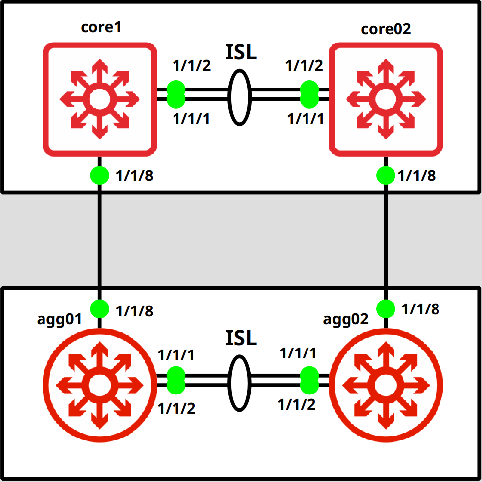
A closeup of the topology.
Let's begin.
MGMT configuration
agg01# configagg01(config)# interface mgmtagg01(config-if-mgmt)# ip static 172.16.40.100/24 // If you want to change it back to DHCP agg01(config-if-mgmt)# ip dhcpagg01(config-if-mgmt)# exit
SSH connection
Now we can connect via SSH.
fedora-kde :: ~ » ssh admin@172.16.40.100
VSX preparation
Ok, now we can start with the VSX configuration.
I will start with the LAG interface. I tend to set the LAG for the ISL on a higher number (128 in this case). But this is not required.
agg01(config)# interface lag 128agg01(config-lag-if)# no routingagg01(config-lag-if)# no shutdown agg01(config-lag-if)# lacp mode activeagg01(config-lag-if)# vlan trunk native 1agg01(config-lag-if)# exit
Next, we will configure and assign the interfaces to the LAG.
agg01(config)# interface 1/1/1,1/1/2agg01(config-if-<1/1/1,1/1/2>)# lag 128agg01(config-if-<1/1/1,1/1/2>)# mtu 9198agg01(config-if-<1/1/1,1/1/2>)# no shutdownagg01(config-if-<1/1/1,1/1/2>)# exit
I will configure an SVI for the VLAN 999 and a separate VRF (the VRF is also not required but recommended) for the heartbeat/keepalive setting in VSX. The best practice would be to set up a dedicated L3 interface for this. But that's not an option in this project.
// Create the VRF
agg01(config)# vrf KEEPALIVEagg01(config-vrf)# exit// Create the VLAN for the keepalive/hearbeat and attach it to the VRF
agg01(config)# vlan 999agg01(config-vlan-999)# name KEEPALIVEagg01(config-vlan-999)# exitagg01(config)# interface vlan 999agg01(config-if-vlan)# vrf attach KEEPALIVEagg01(config-if-vlan)# ip address 10.99.99.1/30The second switch has the exact same configuration, the only difference is the IP address for the keepalive VLAN 999
VSX configuration
That is it for the preparation. It's time for the VSX configuration.
One of the recommended settings is the "system-mac". For this, you should use one of the locally administered address ranges. These are.:
- x2-xx-xx-xx-xx-xx
- x6-xx-xx-xx-xx-xx
- xA-xx-xx-xx-xx-xx
- xE-xx-xx-xx-xx-xx
The idea behind this is, to have an independent system-mac from the hardware mac of the device. This allows smoother hardware replacements in case one of the devices fails since you can just use the same configuration as the previous device without any impact on the VSX.
Let's continue with the configuration.
// Aggregation Switch 1
agg01(config)# vsxagg01(config-vsx)# system-mac 0A:01:00:00:01:00 agg01(config-vsx)# inter-switch-link lag 128agg01(config-vsx)# keepalive peer 10.99.99.2 source 10.99.99.1 vrf KEEPALIVEagg01(config-vsx)# role primaryagg01(config-vsx)# vsx-syncmclag-interfaces neighbor ospf snmp ssh static-routes stp-global vrrp vsx-global
Do the same on the secondary switch. You only have to set the "vsx-sync" on the primary switch.
// Aggregation Switch 2
agg02(config)# vsxagg02(config-vsx)# system-mac 0A:01:00:00:01:00 agg02(config-vsx)# inter-switch-link lag 128agg02(config-vsx)# keepalive peer 10.99.99.1 source 10.99.99.2 vrf KEEPALIVEagg02(config-vsx)# role secondaryagg02(config-vsx)# exitOnce that's done, the VSX Cluster should work. Let's check that. (this is an output from the Simulation since the MPO cables didn't arrive in time).
agg01(config)# show vsx statusVSX Operational State --------------------- ISL channel : In-Sync ISL mgmt channel : operational Config Sync Status : In-Sync NAE : peer_reachable HTTPS Server : peer_reachable Attribute Local Peer ------------ -------- -------- ISL link lag128 lag128 ISL version 2 2 System MAC 0a:01:00:00:01:00 0a:01:00:00:01:00 Platform X86-64 X86-64 Software Version Virtual.10.08.0001 Virtual.10.08.0001 Device Role primary secondary agg01(config)# show vsx briefISL State : In-Sync Device State : Peer-Established Keepalive State : Keepalive-Established Device Role : Primary Number of Multi-chassis LAG interfaces : 0
We can see that everything is reachable and that the switches are in an "In-Sync" state.
Multi-chassis LAG/LACP configuration
Ok, now we will create a LAG/LACP interface, that stretches over both switches in a VSX (MC-LAG). The steps are basically the same as with a single switch. the only difference is in the very first command. Do not forget this step, since you cannot convert a "normal" LAG into a multi-chassis LAG. You would have to remove and recreate it.
// Aggregation Switch 1
agg01(config)# interface lag 1 multi-chassisagg01(config-lag-if)# no routing agg01(config-lag-if)# no shutdown agg01(config-lag-if)# lacp mode active agg01(config-lag-if)# vlan trunk native 1agg01(config-lag-if)# description UPLINK-core01.P1/1/8agg01(config-lag-if)# exitAdd the interface.
// Aggregation Switch 1
agg01(config)# interface 1/1/8agg01(config-if)# lag 1agg01(config-if)# no shutdownagg01(config-if)# description LAG1-UPLINK-core01.P1/1/8agg01(config-if)# exitHere is the configuration for the second switch.
// Aggregation Switch 2
agg02(config)# interface lag 1 multi-chassis agg02(config-lag-if)# no routing agg02(config-lag-if)# no shutdown agg02(config-lag-if)# lacp mode active agg02(config-lag-if)# vlan trunk native 1 agg02(config-lag-if)# description UPLINK-core02.P1/1/8agg02(config-lag-if)# exit// Aggregation Switch 2
agg02(config)# interface 1/1/8 agg02(config-if)# lag 1 agg02(config-if)# no shutdown agg02(config-if)# description LAG1-UPLINK-core02.P1/1/8agg02(config-if)# exitThat's it for the multi-chassis LAG configuration. Let's check if everything is working.
Again this is from a simulation but the output is identical.
agg01(config)# show lacp interfacesState abbreviations : A - Active P - Passive F - Aggregable I - Individual S - Short-timeout L - Long-timeout N - InSync O - OutofSync C - Collecting D - Distributing X - State m/c expired E - Default neighbor state Actor details of all interfaces: ---------------------------------------------------------------------------------- Intf Aggr Port Port State System-ID System Aggr Forwarding Name Id Pri Pri Key State ---------------------------------------------------------------------------------- 1/1/8 lag1(mc) 8 1 ALFNCD 0a:01:00:00:01:00 65534 1 up 1/1/1 lag128 2 1 ALFNCD 08:00:09:05:66:9a 65534 128 up 1/1/2 lag128 3 1 ALFNCD 08:00:09:05:66:9a 65534 128 up Partner details of all interfaces: ---------------------------------------------------------------------------------- Intf Aggr Port Port State System-ID System Aggr Name Id Pri Pri Key ---------------------------------------------------------------------------------- 1/1/8 lag1(mc) 8 1 ALFNCD 08:00:09:3d:5c:7b 65534 10 1/1/1 lag128 2 1 ALFNCD 08:00:09:74:42:09 65534 128 1/1/2 lag128 3 1 ALFNCD 08:00:09:74:42:09 65534 128
You can check the secondary switch with this command. The output looks basically the same.
agg01(config)# show lacp interface vsx-peer
A few more useful "show" commands.
agg01(config)# show lacp aggregates Aggregate name : lag1 (multi-chassis) Interfaces : 1/1/8 Peer interfaces : 1/1/8 Heartbeat rate : Slow Hash : l3-src-dst Aggregate mode : Active Aggregate name : lag128 Interfaces : 1/1/1 1/1/2 Heartbeat rate : Slow Hash : l3-src-dst Aggregate mode : Activeagg01(config)# show lag brief----------------------------------------------------------------------- LAG Type Aggregate Mode Enabled Status Speed Name Mode (Mb/s) ----------------------------------------------------------------------- lag1 multi-chassis active trunk yes up 1000 lag128 inter-switch-link active trunk yes up 2000
VLAN VSX synchronization
A small "bonus" entry. :-) Would be pointless to create a separate post for this.
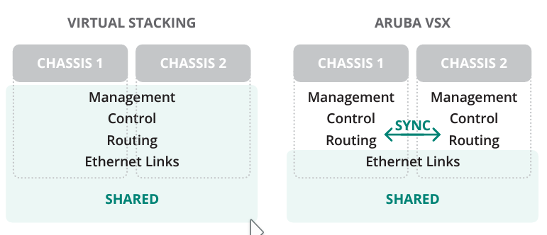
VSX acts more like a cluster than a stack, which means we have two separate management planes. This does not mean that we have to make every change on both switches though. You probably saw earlier that we enabled synchronization for protocols like OSPF or VRRP (See "VSX configuration" of the first switch). Here is a picture taken from an Aruba Document, comparing the traditional stack to VSX to make it a bit clearer.
You might also have noticed that there is no global option for VLAN synchronization.
There is a different way for this. Here is an example.
// Aggregation Switch 1
agg01(config)# vlan 100// this will sync it to the second switch
agg01(config-vlan-100)# vsx-syncagg01(config-vlan-100)# exitYou can see that the VLANs with the "vsx-sync" setting are synced to the secondary device (red), but VLANs 15 and 20 are only on the primary (green) and 30, 35 only on the secondary (purple).
// Aggregation Switch 1
agg01(config)# show running-config... vlan 1,10,15,20vlan 25 vsx-sync vlan 100 vsx-syncvlan 999 spanning-tree ...// Aggregation Switch 2
agg02(config)# show running-config... vlan 1,10 vlan 25 vsx-syncvlan 30,35vlan 100 vsx-syncvlan 999 ...
Below I will attach the configuration of every switch shown in the topology, in case you want to build it yourself.
In the next part, I will go through the configuration of the Aruba 2930F switches including VSF Stacking and Device Profiles for the Aruba APs.
Till next time.
AGG01
[bg_collapse view="link" expand_text="Show More" collapse_text="Show Less"]
hostname agg01
led locator on
vrf KEEPALIVE
!
!
!
!
!
!
ssh server vrf mgmt
vlan 1-2
vlan 10
    name SERVER
    vsx-sync
vlan 20
    name CLIENT
    vsx-sync
vlan 30
    name MGMT
    vsx-sync
vlan 40
    name VOIP
    vsx-sync
vlan 50
    vsx-sync
vlan 60
    vsx-sync
vlan 70
    vsx-sync
vlan 999
spanning-tree
spanning-tree priority 3
spanning-tree config-name STP
spanning-tree config-revision 1
interface mgmt
    no shutdown
    ip dhcp
interface lag 1 multi-chassis
    no shutdown
    description UPLINK-core01.P1/1/8
    no routing
    vlan trunk native 1
    vlan trunk allowed all
    lacp mode active
interface lag 128
    no shutdown
    no routing
    vlan trunk native 1
    vlan trunk allowed all
    lacp mode active
interface 1/1/1
    no shutdown
    mtu 9198
    lag 128
interface 1/1/2
    no shutdown
    mtu 9198
    lag 128
interface 1/1/8
    no shutdown
    lag 1
interface vlan 999
    vrf attach KEEPALIVE
    ip mtu 9198
    ip address 192.168.99.1/30
vsx
    system-mac 0a:01:00:00:01:00
    inter-switch-link lag 128
    role primary
    keepalive peer 192.168.99.2 source 192.168.99.1 vrf KEEPALIVE
    vsx-sync dhcp-server mclag-interfaces neighbor ospf snmp ssh static-routes stp-global vrrp vsx-global
!
!
!
!
!
https-server vrf mgmt
[/bg_collapse]
AGG02
[bg_collapse view="link" expand_text="Show More" collapse_text="Show Less"]
hostname agg02
led locator on
vrf KEEPALIVE
!
!
!
!
!
!
ssh server vrf mgmt
vlan 1
vlan 10
    name SERVER
    vsx-sync
vlan 20
    name CLIENT
    vsx-sync
vlan 30
    name MGMT
    vsx-sync
vlan 35
vlan 40
    name VOIP
    vsx-sync
vlan 50
    vsx-sync
vlan 60
    vsx-sync
vlan 70
    vsx-sync
vlan 999
spanning-tree
spanning-tree priority 3
spanning-tree config-name STP
spanning-tree config-revision 1
interface mgmt
    no shutdown
    ip dhcp
interface lag 1 multi-chassis
    no shutdown
    description UPLINK-core02.P1/1/8
    no routing
    vlan trunk native 1
    vlan trunk allowed all
    lacp mode active
interface lag 128
    no shutdown
    no routing
    vlan trunk native 1
    vlan trunk allowed all
    lacp mode active
interface 1/1/1
    no shutdown
    mtu 9198
    lag 128
interface 1/1/2
    no shutdown
    mtu 9198
    lag 128
interface 1/1/8
    no shutdown
    lag 1
interface vlan 999
    vrf attach KEEPALIVE
    ip address 192.168.99.2/30
vsx
    system-mac 0a:01:00:00:01:00
    inter-switch-link lag 128
    role secondary
    keepalive peer 192.168.99.1 source 192.168.99.2 vrf KEEPALIVE
    vsx-sync dhcp-server mclag-interfaces neighbor ospf snmp ssh static-routes stp-global vrrp vsx-global
!
!
!
!
!
https-server vrf mgmt
[/bg_collapse]
CORE01
[bg_collapse view="link" expand_text="Show More" collapse_text="Show Less"]
hostname core01
led locator on
vrf KEEPALIVE
!
!
!
!
!
ssh server vrf default
ssh server vrf mgmt
vlan 1-2
vlan 10
    name SERVER
    vsx-sync
vlan 20
    name CLIENT
    vsx-sync
vlan 30
    name MGMT
    vsx-sync
vlan 40
    name VOIP
    vsx-sync
vlan 50
    vsx-sync
vlan 60
    vsx-sync
vlan 70
    vsx-sync
vlan 999
    name KEEPALIVE
spanning-tree
spanning-tree priority 2
spanning-tree config-name STP
spanning-tree config-revision 1
interface mgmt
    no shutdown
    ip dhcp
interface lag 1 multi-chassis
    no shutdown
    description UPLINK-agg01.P1/1/8
    no routing
    vlan trunk native 1
    vlan trunk allowed all
    lacp mode active
interface lag 128
    no shutdown
    no routing
    vlan trunk native 1
    vlan trunk allowed all
    lacp mode active
interface 1/1/1
    no shutdown
    mtu 9198
    lag 128
interface 1/1/2
    no shutdown
    mtu 9198
    lag 128
interface 1/1/8
    no shutdown
    description LAG1-UPLINK-agg01.P1/1/8
    lag 1
interface 1/1/9
    no shutdown
interface vlan 30
    ip address 10.155.20.101/24
interface vlan 999
    vrf attach KEEPALIVE
    ip address 10.99.99.5/30
vsx
    system-mac 0a:02:00:00:01:00
    inter-switch-link lag 128
    role primary
    keepalive peer 10.99.99.6 source 10.99.99.5 vrf KEEPALIVE
    vsx-sync dhcp-server mclag-interfaces neighbor ospf snmp ssh static-routes stp-global vrrp vsx-global
ip route 0.0.0.0/0 10.155.20.254
!
!
!
!
!
https-server vrf mgmt
[/bg_collapse]
CORE02
[bg_collapse view="link" expand_text="Show More" collapse_text="Show Less"]
hostname core02
led locator on
vrf KEEPALIVE
!
!
!
!
!
ssh server vrf default
ssh server vrf mgmt
vlan 1
vlan 10
    name SERVER
    vsx-sync
vlan 20
    name CLIENT
    vsx-sync
vlan 30
    name MGMT
    vsx-sync
vlan 40
    name VOIP
    vsx-sync
vlan 50
    vsx-sync
vlan 60
    vsx-sync
vlan 70
    vsx-sync
vlan 999
spanning-tree
spanning-tree priority 2
spanning-tree config-name STP
spanning-tree config-revision 1
interface mgmt
    no shutdown
    ip dhcp
interface lag 1 multi-chassis
    no shutdown
    description UPLINK-agg02.P1/1/8
    no routing
    vlan trunk native 1
    vlan trunk allowed all
    lacp mode active
interface lag 128
    no shutdown
    no routing
    vlan trunk native 1
    vlan trunk allowed all
    lacp mode active
interface 1/1/1
    no shutdown
    mtu 9198
    lag 128
interface 1/1/2
    no shutdown
    mtu 9198
    lag 128
interface 1/1/8
    no shutdown
    description LAG1-UPLINK-agg02.P1/1/8
    lag 1
interface vlan 999
    vrf attach KEEPALIVE
    ip address 10.99.99.6/30
vsx
    system-mac 0a:02:00:00:01:00
    inter-switch-link lag 128
    role secondary
    keepalive peer 10.99.99.5 source 10.99.99.6 vrf KEEPALIVE
    vsx-sync dhcp-server mclag-interfaces neighbor ospf snmp ssh static-routes stp-global vrrp vsx-global
ip route 0.0.0.0/0 10.155.20.254
!
!
!
!
!
https-server vrf mgmt
[/bg_collapse]
Links: